
OpenPnP는 즉시 실행할 수있는 소프트웨어와 구축 및 수정할 수있는 하드웨어 설계를 포함하는 오픈 소스 SMT 픽 앤 플레이스 시스템입니다. 또한 OpenPnP 소프트웨어를 사용하여 자체 디자인의 픽 앤 플레이스 머신을 실행하거나 기존 상용 머신을 사용하여 OEM 소프트웨어로는 제공하지 못했던 기능을 제공 할 수 있습니다.
2021.03.26 led 반도체 가공공장 의뢰로 시작합니다.
처음으로 접하는 시스템이라 너무생소하고
어디부터 시작할지 난감합니다.
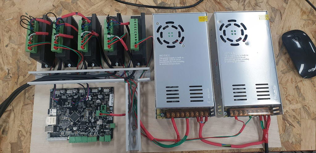
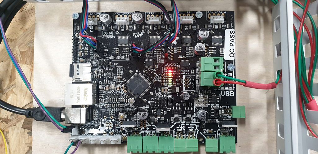
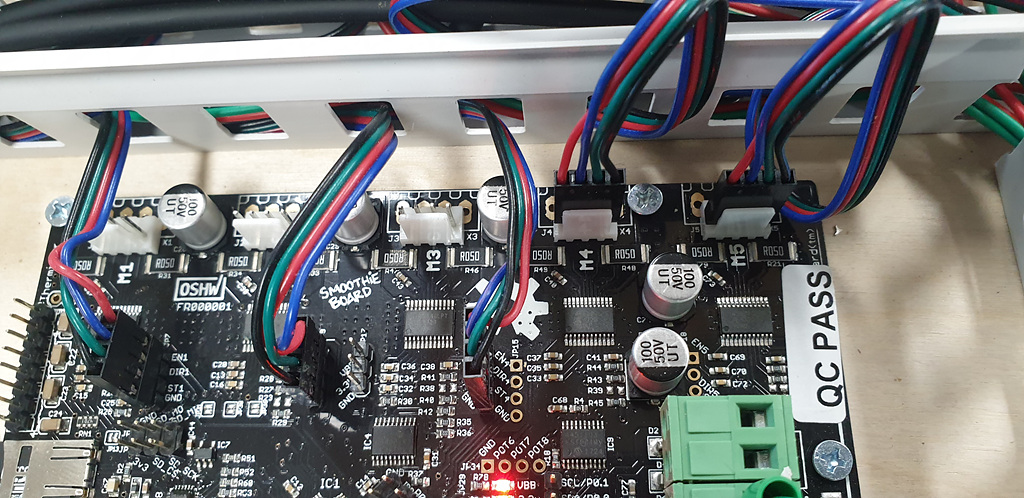
가지고있는 스무디보드가 있어서 먼저
스무디보드 펌웨어부터 시작합니다.
이 보드는 ARM Cortex-M3 칩인 LPC1769 마이크로 컨트롤러를 사용합니다.
1. 먼저 스무스보드를 컴퓨터와 통신을 위하여 usb드라이브를 설치합니다. 아래링크참조
- 32 비트 아키텍처
- 120Mhz 주파수
- 512kB ROM (프로그램 공간)
- 64kB RAM (실행 메모리)\
windows 10 경우에는 자동으로 잡아줍니다.
기존 windows 10 이하 버젼에서는 필히 드라이브 설치를 해주어야 합니다.
http://smoothieware.org/windows-drivers
2.펌웨어 업데이트
이제 보드가 준비되었으므로 시작하기 전에 펌웨어를 최신 버전으로 업데이트하는 것이 좋습니다.
2021.04.26
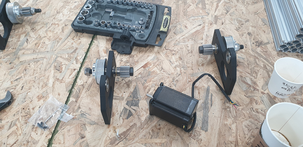
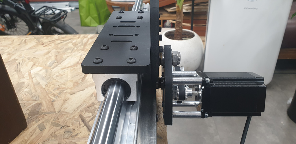
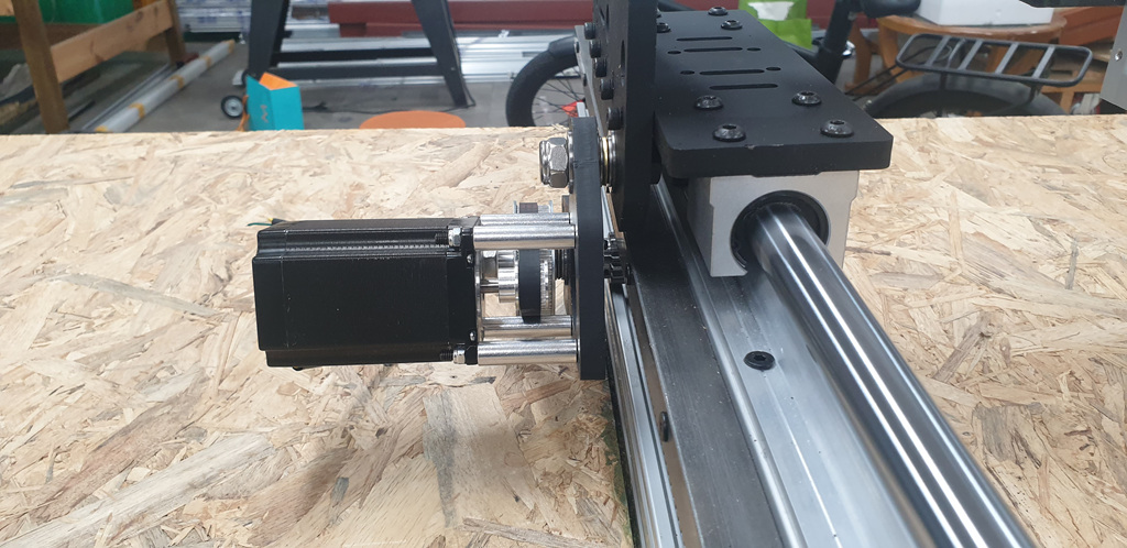
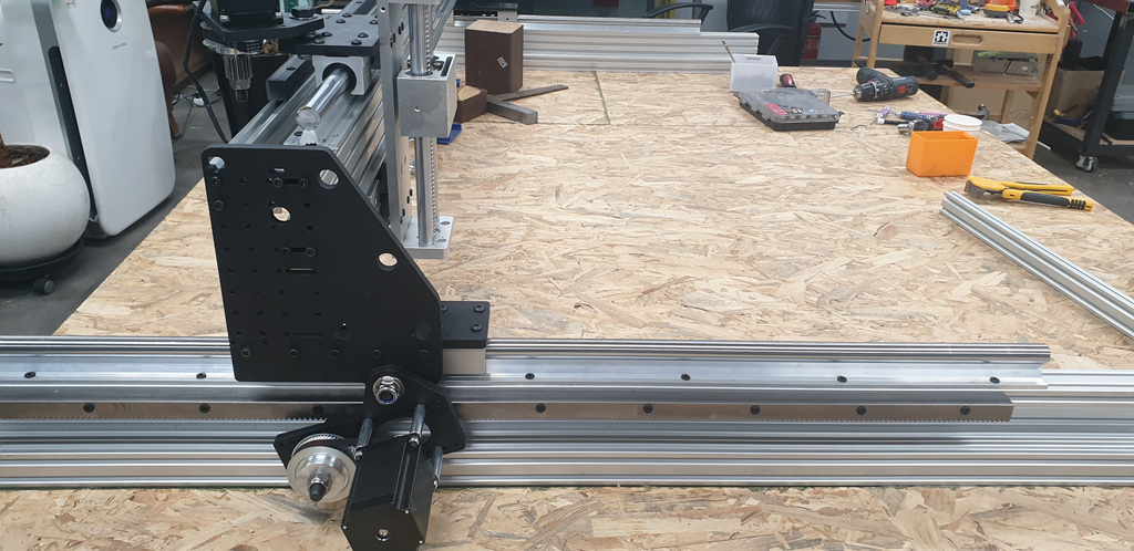
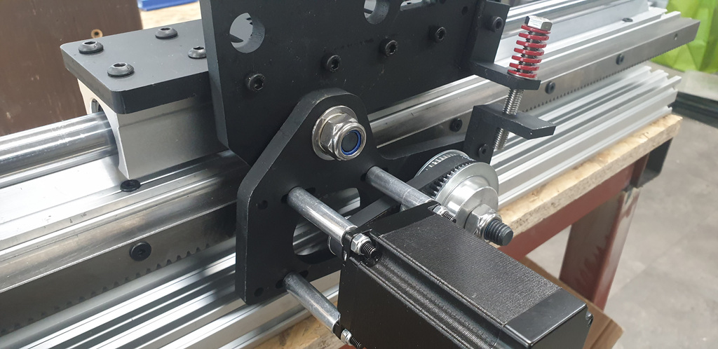
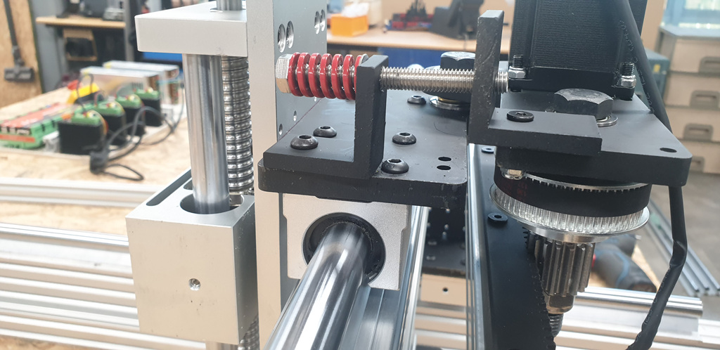
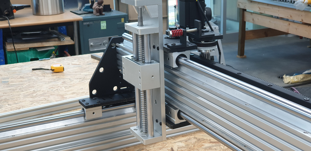
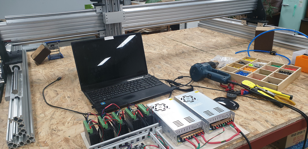
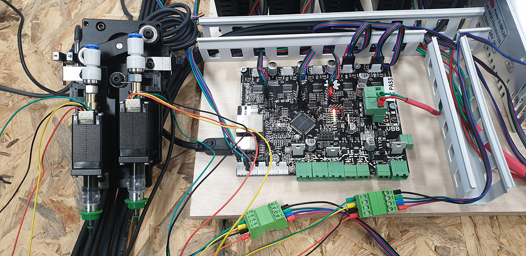
기구부 조립
2021.05.15
펌웨어및 config 수정
최신 Firmware.bin파일 을 다운로드 하고 SD 카드에 복사 한 다음 SmoothieBoard를 재설정하면됩니다.
Flashing Smoothie Firmware 에서 파일 및 플래시 방법에 대한 정보를 찾을 수 있습니다 .
플래싱방법및플래싱 led동작(불규칙적인 led깜밖거림으로 순간적으로 쓰기를 실행합니다.)
SD 카드의 내용을보고 새 펌웨어가 플래시되었는지 확인할 수 있습니다.
펌웨어가 성공적으로 플래시 된 경우 파일 이름이 firmware.bin에서 변경되어야합니다 FIRMWARE.CUR . config.txt는 항상 config.txt로 유지됩니다.
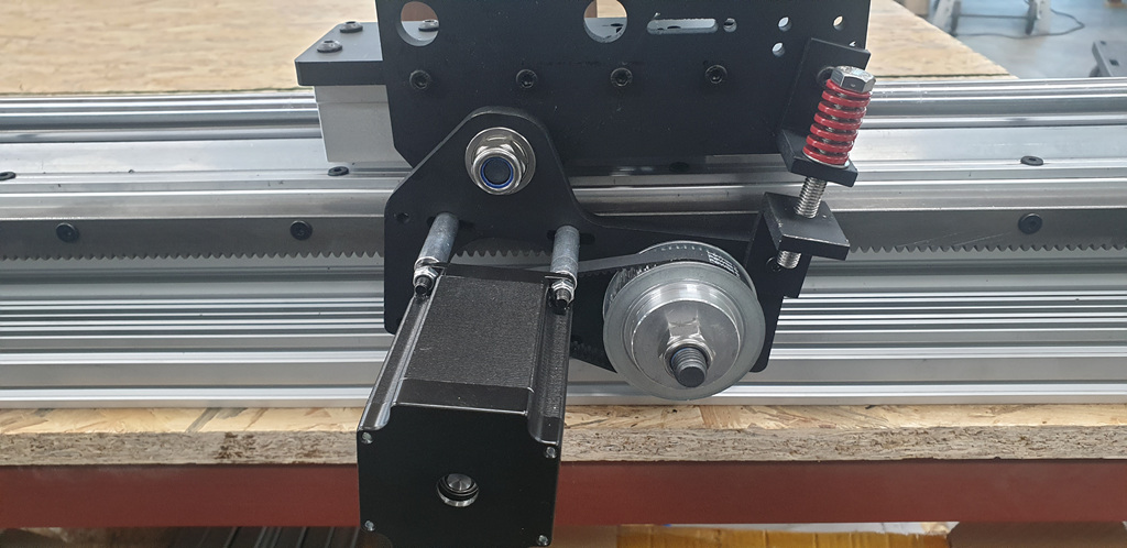
2021.05.20
기구부 조립
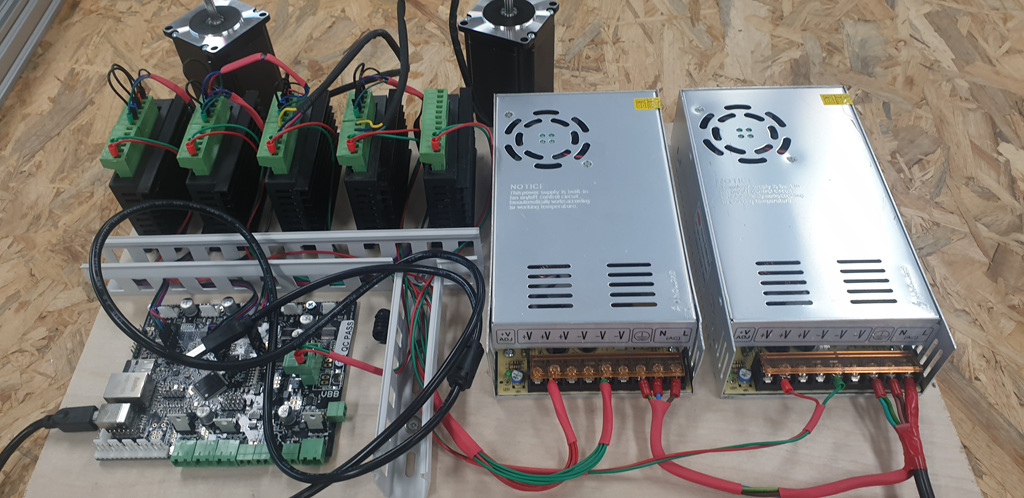
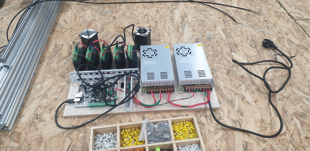
2021.05.22 마이크로 컨트롤러 세팅
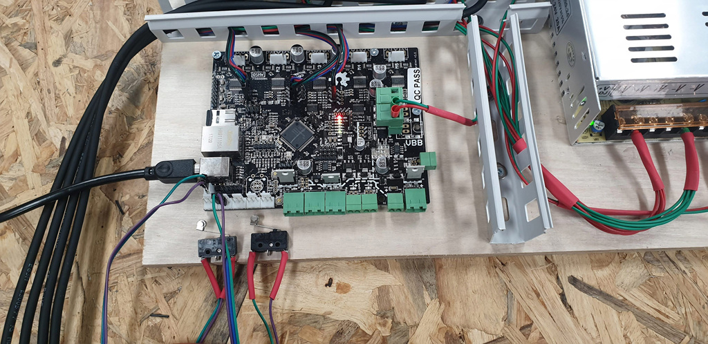
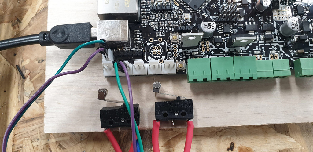
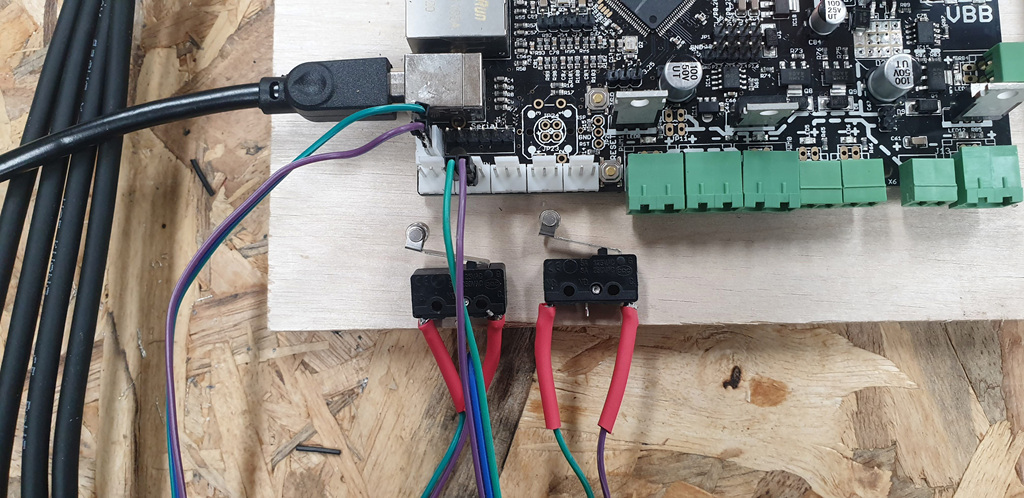
2021.05.23 Endstops 엔드스톱설정및설치
There are 6 endstop connectors, one min and one max per axis. Though you probably just want min for homing, max can be used to limit movement, as can min.
The inputs are 3.3V logic, but 5V tolerant and hardwired with on-board 1k pull-up resistors connected to 3.3V or 5V based on the setting of solder jumper SJ2. The input circuit also contains a series resistor so you generally need to use a sensor or switch which actively switches to GND.
Each endstop connector is a 3-pin 2.54mm, providing Vcc, GND, and the actual input endstop pin. (Vcc is either 3.3V or 5V depending on the state of solder jumper SJ2).
Smoothieboard - Smoothie Project (smoothieware.github.io)
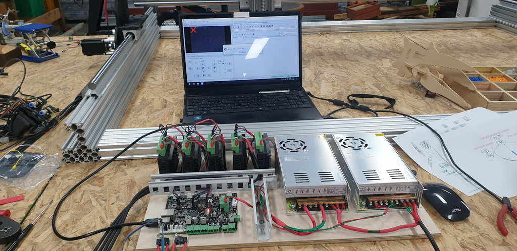
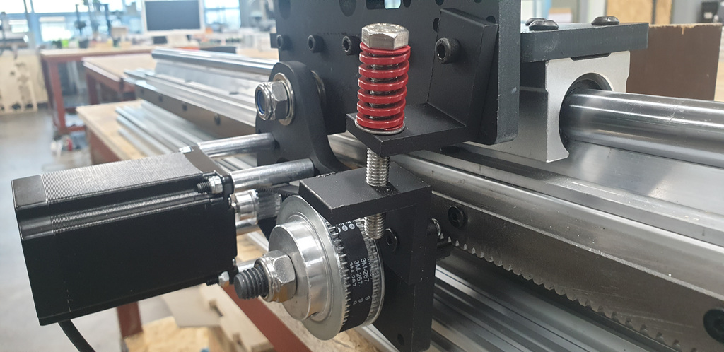
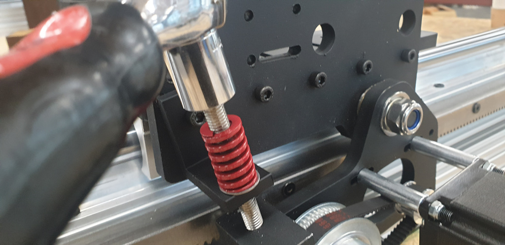
2021.05.25 마이크로 컨트롤러 세팅및 cam 설치
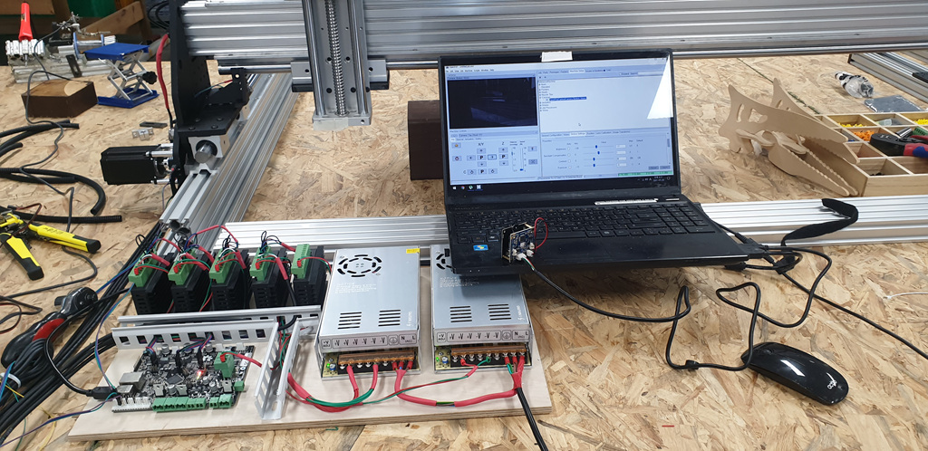
2021.05.25 마이크로 컨트롤러 config.txt 설정
config20210525일날최종수정파일.txt 첨부파일 아래에서 다운
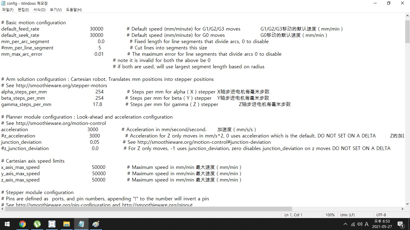
0.01 단위 ~100 mm 단위까지
세팅동영상
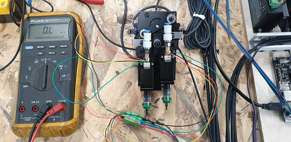
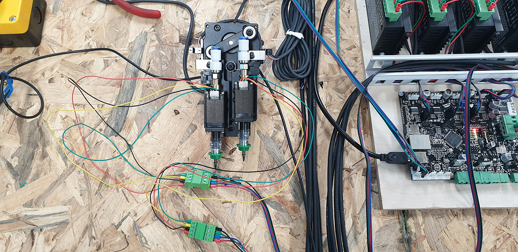
2021.05.26
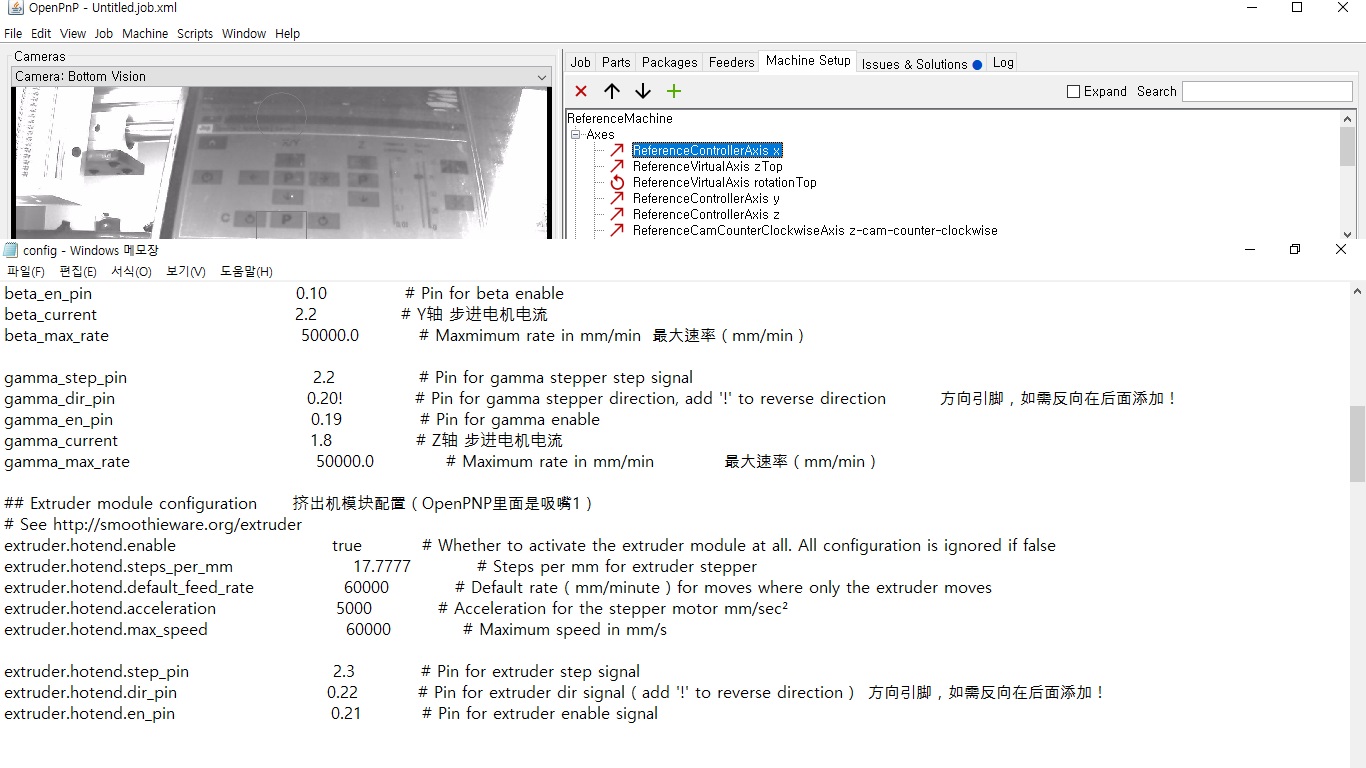
마이크로 컨트롤러 dual nozzle 설치
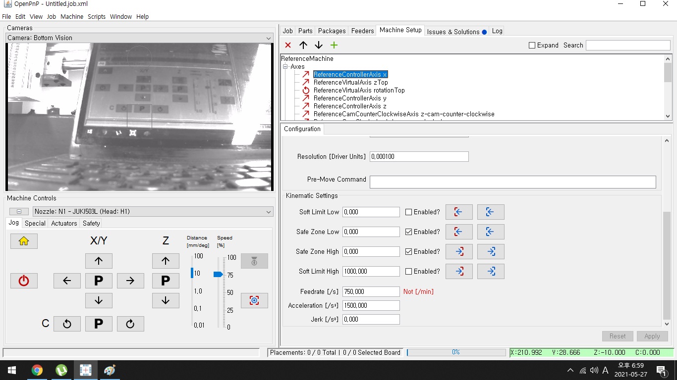
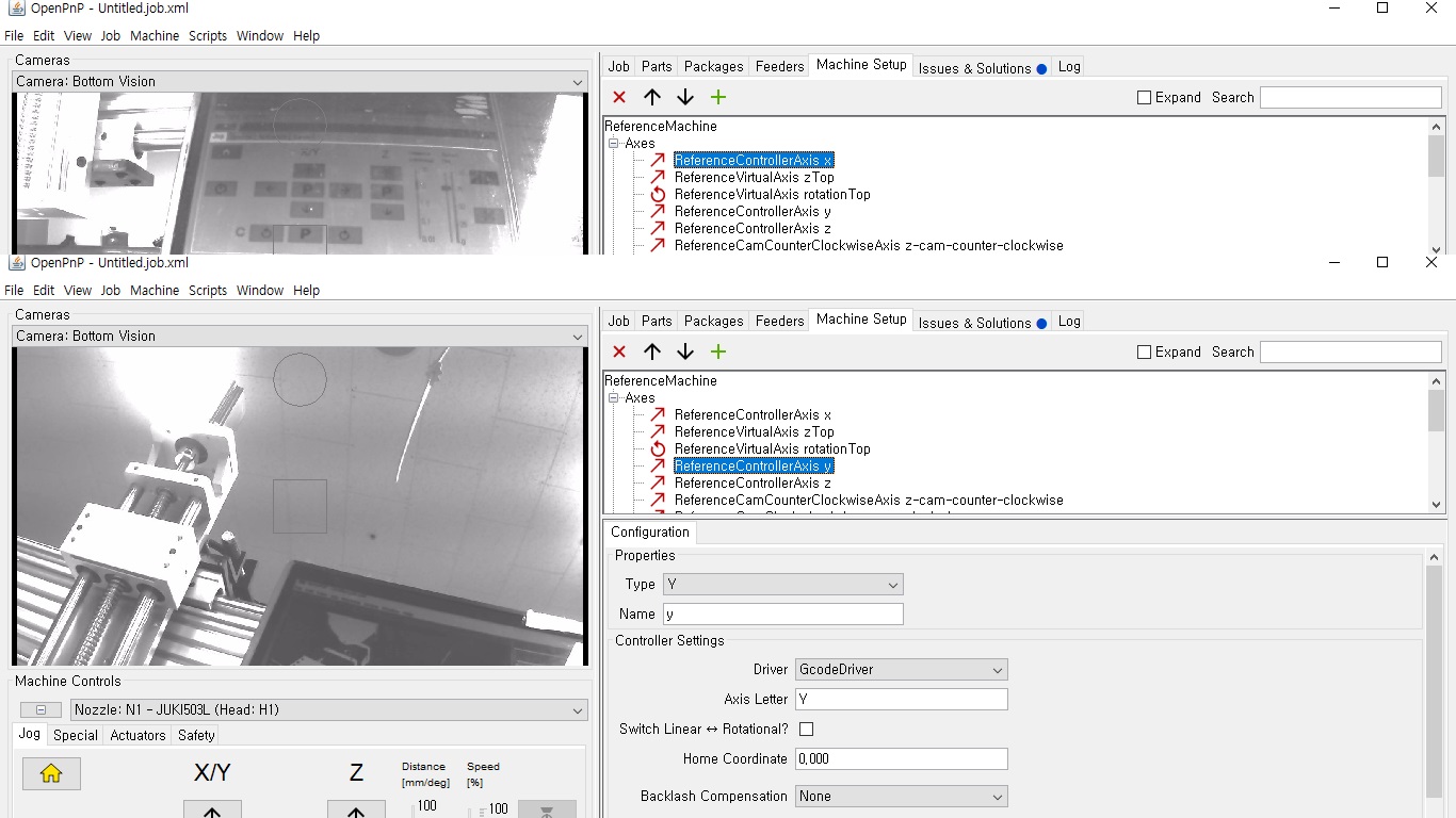
ReferenceControllerAxis x 1번화면
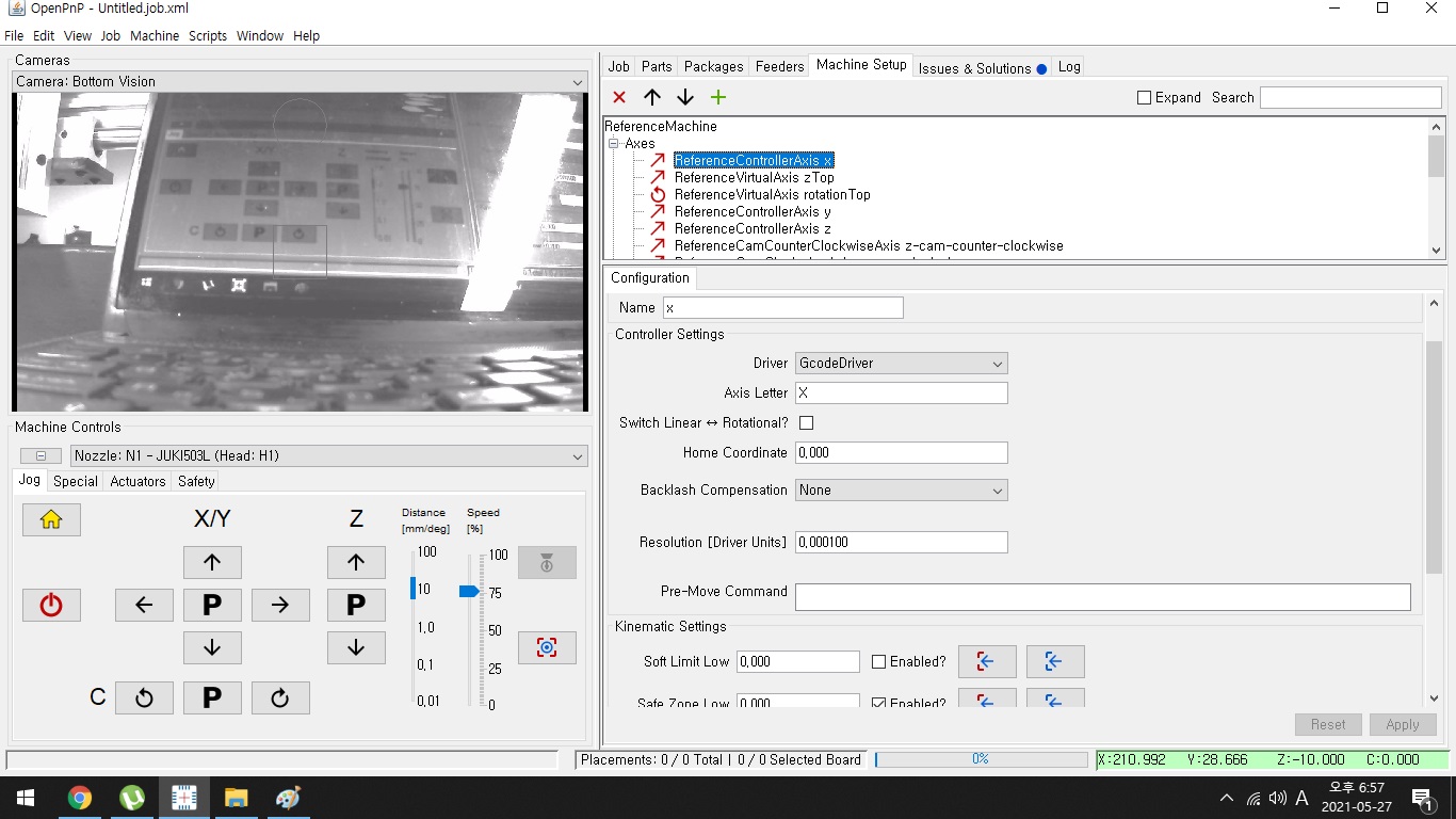
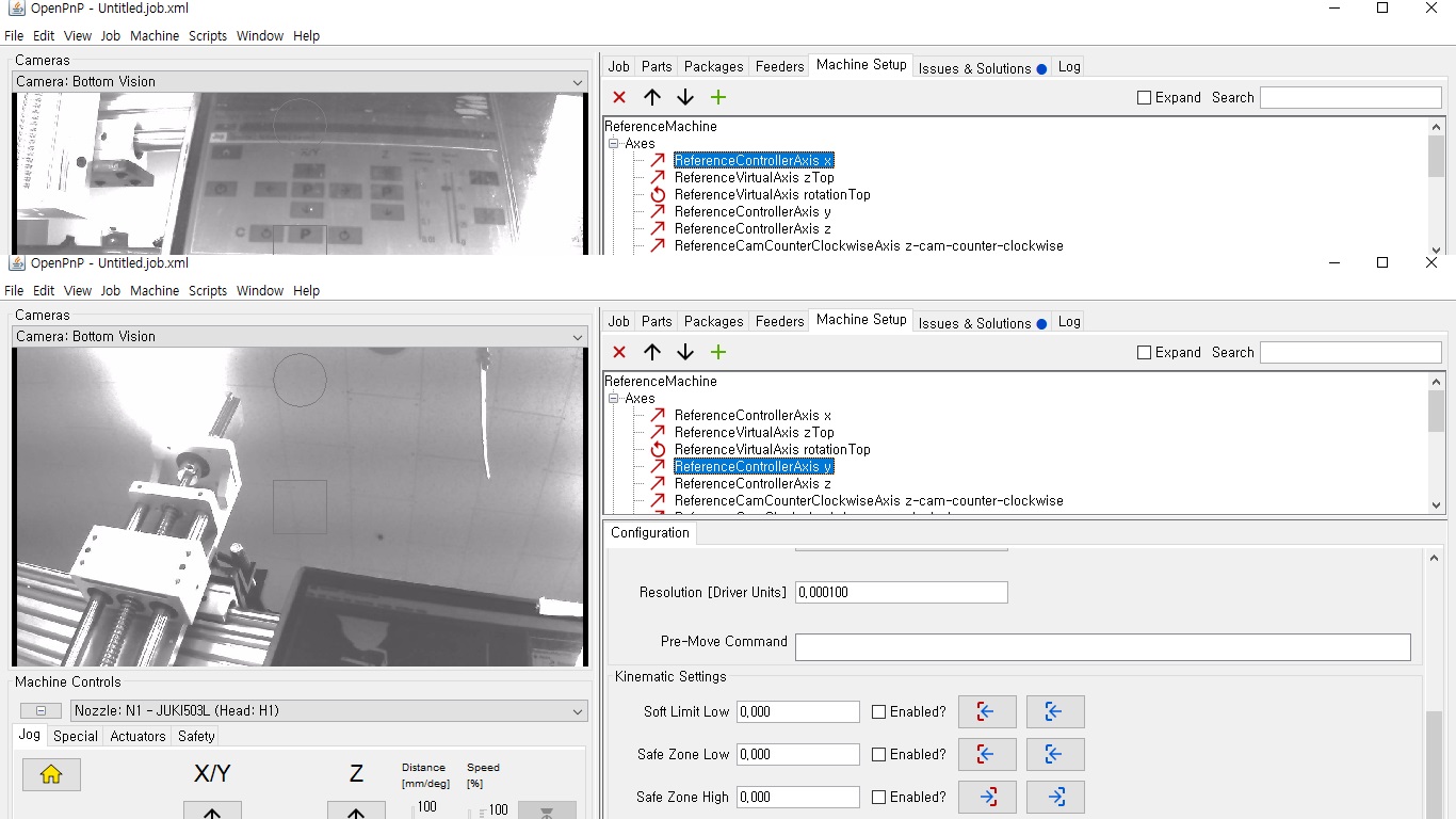
ReferenceControllerAxis x 2번화면
ReferenceControllerAxis y 1번화면
ReferenceControllerAxis y 2번화면
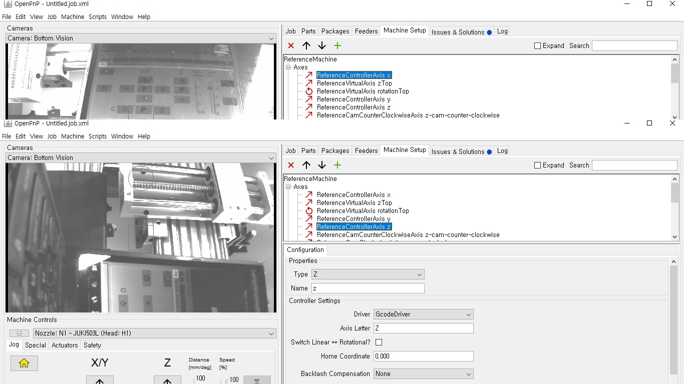
ReferenceControllerAxis z 1번화면
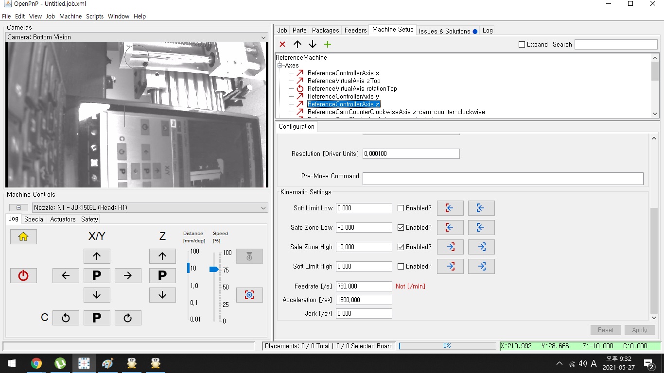
ReferenceControllerAxis z 2번화면
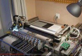
openpnp 오픈 소스 SMT 픽 앤 플레이스 시스템
Article in 'Programming' published by kiminhan, Jun 13, 2021.
OpenPnP는 즉시 실행할 수있는 소프트웨어와 구축 및 수정할 수있는 하드웨어 설계를 포함하는 오픈 소스 SMT 픽 앤 플레이스 시스템입니다. 또한 OpenPnP 소프트웨어를 사용하여 자체 디자인의 픽 앤 플레이스 머신을 실행하거나 기존 상용 머신을 사용하여 OEM 소프트웨어로는 제공하지 못했던 기능을 제공 할 수 있습니다. 2021.03.26 led 반도체 가공공장 의뢰로 시작합니다. 처음으로 접하는 시스템이라 너무생소하고 어디부터 시작할지 난감합니다.
- Loading...
-
- 빌드진행상황:
-
- 빌드작업진행중입니다.
-
부품목록
수량 부품이름 부품링크 부품정보댓글 기타 1 ARM Cortex-M3 칩인 LPC1769 마이크로 컨트롤러 Link ARM Cortex-M3 칩인 LPC1769 마이크로 컨트롤러 ARM Cortex-M3 칩인 LPC1769 마이크로 컨트롤러
© XenZine Articles from Pick a Tutor